PIPE NETWORK
3 CONDITIONS NEED TO STATISFY:
1. At any junction, the
flow into a junction equals the flow out of the junction.
2. Between any two junctions, the head loss is independent of the path taken
3. Each flow must satisfy the friction law in pipe

-First, we need to GUESS the values for
the flow in network. For example, if Q7 enters a junction, and Q6 and Q4 leave
the same junction. The initial guess Q7=Q6+Q4.
First condition
A loop is considered. Next, we need to
evaluate our second condition.
Given a starting node, we work our way
around the loop in a clockwise fashion, as illustrated by Loop 1.
We add up the head losses according to
the Darcy–Weisbach equation for each pipe if Q is in the same direction as our
loop like Q1, and subtract the head loss if the flow is in the reverse
direction, like Q4.
In order to satisfy the second
condition, we should end up with 0 about the loop if the network is completely
solved. If the actual sum of our head loss is not equal to 0, then we will
adjust all the flows in the loop by an amount given by the following formula,
where a positive adjustment is in the clockwise direction.
Where
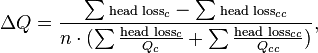
where
- n is 1.85 for
Hazen-Williams and
- n is 2 for Darcy–Weisbach.
The clockwise specifier (c) means
only the flows that are moving clockwise in our loop, while the
counter-clockwise specifier (cc) is only the flows that are moving counter-clockwise.


EXAMPLE 1

For this example, the in
and out flows will be 10 liters per second. We will consider n to be 2, and the
head loss per unit flow r, and initial flow guess for each pipe as
follows:
Pipe
|
Q12
|
Q13
|
Q23
|
Q24
|
Q34
|
r
|
1
|
5
|
1
|
5
|
1
|
Q
guess (L/s)
|
5
|
5
|
0
|
5
|
5
|
1. The initial guesses are set up so that continuity
of flow is maintained at each junction in the network.
2. The loops of the system are identified as loop
1-2-3 and loop 2-3-4.
3. The head losses in each pipe are determined.
Loop 1-2-3
|
Q12
|
Q13
|
Q23
|
Head loss =
 |
25
|
125
|
0
|
Direction
|
Clockwise
|
Counter-clockwise
|
Clockwise
|
For loop 1-2-3, the sum of the clockwise head losses
is 25 and the sum of the counter-clockwise head losses is 125.
Loop 2-3-4
|
Q23
|
Q24
|
Q34
|
Head loss =
|
0
|
125
|
25
|
Direction
|
Counter-clockwise
|
Clockwise
|
Counter-clockwise
|

Pipe
|
Q12
|
Q13
|
Q23
|
Q24
|
Q34
|
Original Q
|
5
|
5
|
0
|
5
|
5
|
Change in flow
|
1.66
|
-1.66
|
Total of change in flow :
 |
-1.66
|
+1.66
|
Q (L/s)
|
6.66
|
3.33
|
3.33
|
3.33
|
6.66
|
The process then repeats from step 3 until the
change in flow becomes sufficiently small or goes to zero.
4. The
total lead loss in Loop 1-2-3 is
Loop 1-2-3
|
Q12
|
Q13
|
Q23
|
Head loss =
|
44.4
|
55.5
|
11.1
|
Direction
|
Clockwise
|
Counter-clockwise
|
Clockwise
|
Total head loss in
clockwise direction = 44.1+11.1 =55.5
Total head loss in counter-clockwise
direction=55.5
Clockwise head loss=
Counter clockwise head loss
This means that the
flow in this loop is balanced and the flow rates are correct. The total head
loss in loop 2-3-4 will also be balanced (again due to symmetry).
Loop 2-3-4
|
Q23
|
Q24
|
Q34
|
Head loss =
|
11.1
|
55.5
|
44.4
|
Direction
|
Counter-clockwise
|
Clockwise
|
Counter-clockwise
|
Total head loss in
clockwise direction= 55.5
Total head loss in
counter-clockwise direction= 11.1 + 44.4 =55.5
In this case, the
method found the correct solution in one iteration. For other networks, it may
take multiple iterations until the flows in the pipes are correct or
approximately correct.
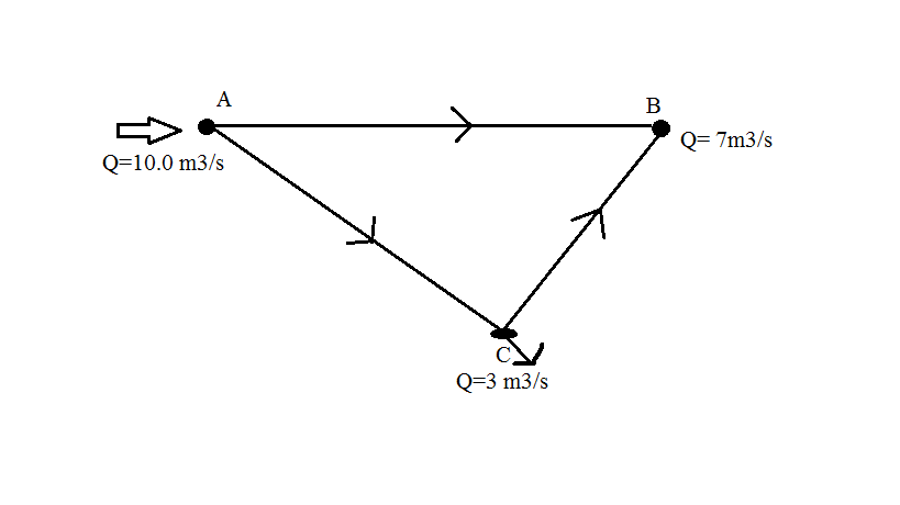
EXAMPLE 2
Find discharge Q in
every water pipes for the water supply system by using Hardy-Cross method and Darcy
Weisbach equation. Neglect minor losses in pipes:
Pipe
|
AB
|
BC
|
CA
|
Length (mm)
|
600
|
600
|
200
|
Diameter (mm)
|
250
|
150
|
100
|
Friction factor, f
|
0.0039
|
0.0044
|
0.0051
|

Since dQ₂ = 0, the Q₂ is correct. Pipe AB has 8.4566 m3/s flow. Pipe AC has 1.5466 m3/s flow (counter-clockwise direction) and pipe CB has 1.4566 m3/s flow.
No comments:
Post a Comment